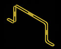
Tray
Reducer-Cable Tray-Cabletray-Cable Trays- Cable Tray Systems- Raceway Systems
American Tele Data
Tele Data Is Your One Source For All Your Cable Tray-Cable Trays- Cable Tray
Systems- Basket Tray- Raceway Systems
Cable-Mgr-Save
50% On Cable Tray Installation Costs
American Tele Data
carries raceway systems and Cable Tray from Cable Manger due to Cable-Mgr.'s innovative
cable tray, and extensive cable tray systems design which are based on pre-fabricated
junctions/intersections and the ability to provide powder coated finishes while
maintaining grounding. The design eliminates the need to cut or bend sections
or install a separate ground wire. Cable-Mgr. is U.L. classified as to its suitability
as an equipment grounding conductor only.No connecting hardware required. All
support hardware available. Powder coating is standard finish.Custom sizes available.
Furthermore, Cable-Mgr.'s wire grid cable tray systems require only one tool and
very few accessory items for installation. Pre-fabricated junctions/intersections
reduce man-hours by eliminating cutting and fabrication in the field. With center
hung trapeze, wall or floor mount accessories, Cable-Mgr. is prepared to handle
the toughest installations
We
now accept Visa,Discover Master Card & AMEX
-
Center Support Installation Hardware |
Cable
tray-CM50 - 1/4 inch Threaded Rod Kit. Includes (1) 1/4 inch coupling nut,
(2) 1/4 inch flat washer, (2) 1/4 inch nuts and(1) 6 inch silicione protective
tube. Threaded rod not included.CM51 - 3/8 inch Threaded Rod Kit. Includes (1)
3/8 inch coupling nut, (2) 3/8 inch flat washer, (2) 3/8 inch nuts and (1) 6 inch
silicone protective tube. Threaded rod not included.
Catalog Numbering System
(example below is for an 8 inch center hung tray using 1/4 inch threaded rod
CM
50 08
Tray
Widths: 2 inch = 02, 4 inch = 04, 6 inch = 06, 8 inch = 08, 12 inch = 12
Trapeze Support Installation Hardware |
CM52
- 1/4 inch Threaded Rod Kit. Includes (2) 1/4 inch coupling nuts, (4) 1/4
inch flat washers and (4) 1/4 inch nuts. Threaded rod not included.
CM53
- 3/8 inch Threaded Rod Kit. Inclueds (2) 3/8 inch coupling nuts, (4) 3/8
inch flat washers and (4) 3/8 inch nuts. Threaded rod not included.
Catalog
Numbering System (example below is for an 18 inch trapeze hung tray using 3/8
inch threaded rod)
CM
53 18
Tray
Widths: 6 inch= 06, 8 inch= 08, 12 inch= 12, 18 inch= 18, 24 inch= 24
 4 inch height, available widths 2, 4, 6, 8, 12, 18 and 24 inches.
Catalog Numbering
System (example below is for an 8 inch wide raised floor support)
CM56
08
Widths:
2 inch = 02, 4 inch = 04, 6 inch = 06, 8 inch = 08, 12 inch = 12, 18 inch = 18,
24 inch = 24
Coupling
Nuts
CM60 1/4 in.
CM61 3/8 in. | Flat
Washers
CM62 1/4 in.
CM63 3/8 in. | Finned
Nuts
CM65 1/4 in.
CM66 3/8 in.
CM67 5/16 in | Carriage
Bolts
CM68 5/16 in. x 3/4 in.
CM72* 5/16 in. x 1 1/4 in | Protective
Tubing
CM69
6 in. for
1/4 in. & 3/8 in. rod |
Center
Support
CM54xx
Widths
02, 04, 06, 08, 12 inches | Trapeze
Support
CM55xx
Widths
06, 08, 12, 18, 24 inches | Wall
Mount*
CM57xx
Widths
02, 04, 06, 08, 12, 18, 24 inches*Anchor to floor
or wall using 3/8 inch bolt & washer. Anchor hardware not included. | Tray
Extension
CM58xx | Waterfall
CM5902
(4 inch width)
02 = Ø.187" | Universal
Loop**
CM70xx
02 = Ø.187"
03 = Ø.250" **Use 1
5/16 inch bolt on double loop end |
-
What
is Cable Tray?
1. What is a Cable Tray System?
2. What standards / guidelines are available
for cable tray systems?
3. What types of Cable Tray are available?
4.
How do I know what type of cable tray is right for my application?
5. What
materials / finishes are available for the various cable tray systems?
6.
Now that I know what types of cable trays are available, what configurations are
available?
7. After selecting the type of cable tray and configuration required,
what support methods are available?
8. Before selecting the type of cable
tray, cable tray configuration(s), and support method desired, what additional
information do I need to supply to the cable tray manufacturer for them to best
understand and satisfy my needs?
What
is a Cable Tray System?
Per
the National Electrical Code, a cable tray system is "a unit or assembly
of units or sections and associated fittings forming a rigid structural system
used to securely fasten or support cables and raceways."
What does this
mean?
* Cable trays support cable the way that roadway bridges support traffic.
* A bridge is a structure that provides safe passage for traffic across open spans.
* Cable tray is the bridge that allows for safe transport of wires across open
spans.
* Therefore, think of cable tray as the structural component of a building's
electrical system.
What
standards / guidelines are available for cable tray systems?
1. The National Electrical Code publishes the standards for all types of electrical
applications. Articles 318, 250, and 800 cover various aspects of cable tray systems.
2. NEMA, (National Electrical Manufacturers Association), is an association comprised
of the major cable tray manufacturers in the industry. This committee has published
three documents to date: NEMA VE1, FG1 and VE2.
NEMA VE1 covers general cable tray definitions, manufacturing standards, performance
standards, test standards, and application information. Free download of this
document is available on the NEMA website.
NEMA FG1 addresses the standards for fiberglass cable tray systems. Free download
of this document is available on the NEMA website.
NEMA VE2 is a cable tray installation guideline which covers receiving and unloading
material, storage of material, and general installation practices. Free download
of this document is available on the NEMA website.
3. CTI, (Cable Tray Institute),
is a trade association comprised of the major cable tray manufacturers in the
industry and was formed to provide specifiers, designers, and installers information
on the advantages of using cable tray systems over other types of products. (i.e.
conduit, ladder rack, etc.)
What
types of Cable Tray are available?
1. Ladder
2. Solid Bottom
3. Trough
4. Channel
5. Wire Mesh
6. Single Rail
How
do I know what type of cable tray is right for my application?
1. Ladder Cable Tray provides:
1. Solid side rail protection and system strength
with smooth radius fittings and a wide selection of materials and finishes.
2. maximum strength for long span applications
standard widths of 6,12,18,
24, 30, and 36 inches
3. standard depths of 3, 4, 5, and 6 inches
4. standard
lengths of 10, 12, 20 and 24 feet
5. rung spacing of 6, 9, 12, and 18 inches
Ladder cable tray is generally used in applications with intermediate to
long support spans, 12 feet to 30 feet.
2. Solid Bottom Cable Tray provides:
1. Nonventilated continuous support for delicate cables with added cable protection
available in metallic and fiberglass.
2. Solid bottom metallic with solid
metal covers for nonplenum rated cable in environmental air areas
3. standard
widths of 6, 12, 18, 24, 30, and 36 inches
4. standard depths of 3, 4, 5,
and 6 inches
5. standard lengths of 10, 12, 20 and 24 feet
Solid Bottom
cable tray is generally used for minimal heat generating electrical or telecommunication
applications with short to intermediate support spans of 5 feet to 12 feet.
3. Trough Cable Tray provides:
1. Moderate ventilation with added cable
support frequency and with the bottom configuration providing cable support every
4 inches. Available in metal and nonmetallic materials.
2. standard widths
of 6, 12, 18, 24, 30, 36 inches
3. standard depths of 3, 4, 5, and 6 inches
4. standard lengths of 10, 12, 20 and 24 feet
5. fixed rung spacing of 4 inch
on center
Trough cable tray is generally used for moderate heat generating
applications with short to intermediate support spans of 5 feet to 12 feet.
4. Channel Cable Tray provides:
1. an economical support for cable drops
and branch cable runs from the backbone cable tray system.
2. standard widths
of 3, 4, and 6 inches in metal systems and up to 8 inches in nonmetallic systems.
3. standard depths of 1¼-1¾ inches in metal systems and 1, 1 1/8,
1 5/" and 2 3/16 inches in nonmetallic systems
4. standard length of
10, 12, 20 and 24 feet
Channel cable tray is used for installations with
limited numbers of tray cable when conduit is undesirable. Support frequency with
short to medium support spans of 5 to 10 feet.
5. Wire Mesh Cable Tray
provides:
1. A job site, field adaptable support system primarily for low
voltage, telecommunication and fiber optic cables. These systems are typically
steel wire mesh, zinc plated.
2. standard widths of 2, 4, 6, 8, 12, 16, 18,
20, and 24 inches
3. standard depths of 1, 2, and 4 inches
4. standard
length of about 10 feet (118")
Wire Mesh tray is generally used for
telecommunication and fiber optic applications and are installed on short support
spans, 4 to 8 feet.
6. Single Rail Cable Tray provides:
1. These
aluminum systems are the fastest systems to install and provide the maximum freedom
fort cable to enter and exit the system.
2. Single hung or wall mounted systems
in single or multiple tiers.
3. Standard widths are 6, 9, 12, 18, and 24 inches.
4. Standard depths are 3, 4, and 6 inches.
5. Standard lengths are 10 and
12 feet.
Single Rail Cable Tray is generally used for low voltage and power
cables installations where maximum cable freedom, side fill, and speed to install
are factors.
What
materials / finishes are available for the various cable tray systems?
1. Steel (Min. Yield = 33KSI) (35 KSI for Stainless)
1. Plain: hot rolled
pickled and oiled steel per ASTM A569 (Commercial Quality) or A570 (Structural
Quality)
2. Pre-Galvanized: mill galvanized steel per ASTM A653 CS (Commercial)
or SS (Structural) G90
3. Hot Dip Galvanized After Fabrication: plain steel
which is hot dipped after fabrication per ASTM A123.
4. Stainless Steel: type
304 or 316L fully annealed stainless steel
2. Aluminum (Min.Yield =
23 KSI)
1. 6063-T6 or 5052-H32 alloy per ASTM B209
3. Fiber Reinforced
Plastic (FRP)
1. Polyester and Vinyl Ester resin systems available
2.
meet ASTM E-84 smoke density rating; Polyester 680, Vinyl Ester 1025
3. Class
1 Flame Rating and self-extinguishing requirements of ASTM D-635.
Now
that I know what types of cable trays are available, what configurations are available?
1. Straight sections are available to route cables in a horizontal or vertical
plane.
2. Fittings are available to route cables in various directions in
either the horizontal or vertical planes. Typical examples of fittings include
elbows, tees, crosses, and risers. Each of these fittings are available in various
radii and bend angles.
3. Covers are accessories and shouldn't be in here
unless splices etc. are included.
After
selecting the type of cable tray and configuration required, what support methods
are available?
1. Trapeze Support (Single or Multi-tier)
2. Hanger rod clamps, "J"
hangers
3. Center Hung Support
4. Wall Support
5. Underfloor Support
6. Pipe stanchions or other structures
Each
of these support methods are preferable in different applications. For instance,
trapeze supports may be desired in an application where cables will be pulled
through the cable tray. Center hung supports, on the other hand, are generally
used when cables will be installed from the side of the cable tray. Center hung
supports are especially useful when future cable additions are desired. Wall supports
and underfloor supports are useful when ceiling structure is not available or
undesired. Outdoor installations are controlled by the structures available to
support the cable tray.
Before selecting the type of cable tray, cable tray
configuration(s), and support method desired, what additional information do I
need to supply to the cable tray manufacturer for them to best understand and
satisfy my needs?
1. Where? Job site and installation considerations
1. Outdoor
1. supports
available affect the length and strength requirements
2. environmental loads,
ice, wind, snow, and possibly seismic
3. corrosion requirements affect the
materials and finishes
4. classified hazardous locations affect the cable
types acceptable
2. Indoor
1. support locations available affect the
length and strength of the system
2. industrial installation may require a
200 lb. Concentrated Load
3. commercial or institutional installation may
make system appearance, system weight, and space available important factors
4. environmental air handling area may affect cable types, cable tray material,
or cable tray type and need for covers
5. classified hazardous locations affect
the cable types acceptable
2. What?
1. Type and number of cables to support
1. NEC cable fill requirements
dictate size, width and depth, of system
2. cable support requirement may
control bottom type
3. largest bending radius of cable controls fitting radius
4. total of cable weight determines load to support
2. Future requirements
1. cable entry / exit freedom
2. design partially full or an expandable system
3. support type to allow for needs
Key
Features- Applications
• Requires NO bending or cutting; ready–made 4-way, “T” and
“L” shaped junctions
• Conforms to the National Electric Code,
UL Classified
• Acts as a continuous ground conductor; no grounding splices
• Adapts to difficult architectural designs to accommodate changes in direction
and elevation of cable runs
• Cuts installation time up to 50 percent
• Provides strength, rigidity without additional hardware; has smooth edges
• Manufactured in an array of protective, powder-coated, colored finishes
to minimize corrosion
• Featured in light or heavy duty product styles
• All support hardware available
• Powder coating is standard finish
• Custom sizes available
LOW
PRICE GUARANTEE:  American Tele Data will NOT
BE UNDERSOLD. Just provide us with a written quote from any US competitor
and American Tele Data will MEET or BEAT their price! Call Us For Additional Details At
(866) 342-3721 American Tele Data will NOT
BE UNDERSOLD. Just provide us with a written quote from any US competitor
and American Tele Data will MEET or BEAT their price! Call Us For Additional Details At
(866) 342-3721 |
We’re
here to help you solve your business challenges and increase your ability to meet
your own customers’ growing expectations from their telecommunications service
providers.